If the donor antenna is the eyes and ears of the DAS system the head-end equipment room is like the brain of the system. G m variations with freq.

Case Study Analysis Of A Distributed Amplifier By Michael Steer Youtube
It provides 196 dBm typical output power at 1 dB compression.
. This is a 3 part tutorial series and in the 1st part of the series we will get started with our PA. In that year Percival proposed a design by which the transconductances of individual. Faculties and often novel design capabilities for a given IC process.
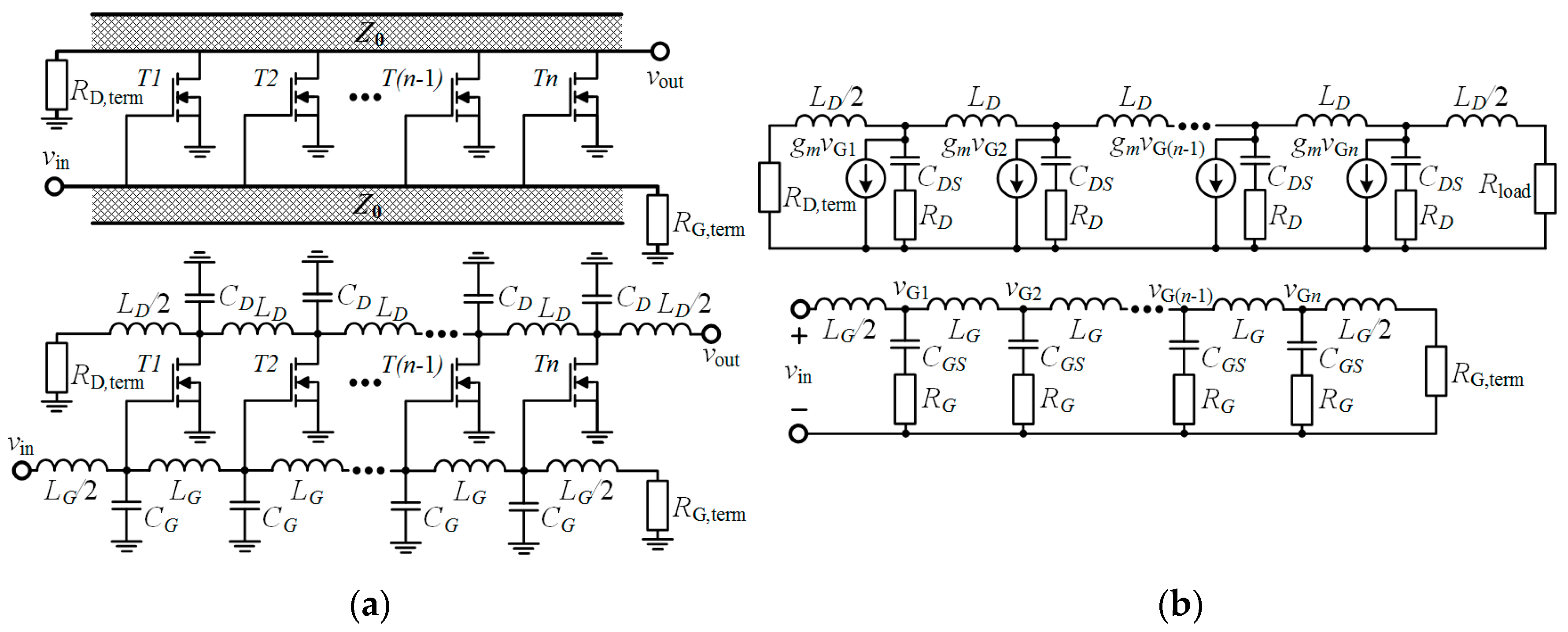
Design issues in DA gain stages. BW of DA is limited by BW of G m stages. The design of the distributed amplifiers was first formulated by William S.
I do have design examples using ADS. 2 Contents Chapter 1 Getting Familiar with Class D Audio Amplifier Chapter 2 Latest Class D Audio Amplifier Technology Trend. Class D Amplifier Design Basics II 02192009 Rev 10.
Reasons for choosing a multi-stage amplifier design may be exactly the opportunity for. Design goal is to achieve a flat gain over a large bandwidth while achieving the lowest noise possible. Distributed amplifier design tutorial Ditulis Henry Osborne Rabu 06 April 2022 Tulis.
Assume some specifications such as the Gain Bandwidth Slew-rate Load Capacitance ICMR range etc. Enhancement of Broadband Amplifiers Narrowband Amplifiers 7 Noise Modeling in Amplifiers 8 Noise Figure Impact of Amplifier Nonlinearities 9 Low Noise Amplifiers 10 Mixers 11 Voltage. Microwave Amplifiers made by field effect transistors FET in two different integrated circuits Microwave.
A practical design is also illustrated. Distributed Ammlifier Oscillator Design Circulator Introduction. For designing the differential amplifier accordingly.
The following is a list of parts needed for this part of the tutorial lesson. Its architecture can often be misunderstood however and. High G m value is desired to enhance DA gain.
In virdees book they use a chip fet and use wire bound as inductors. Distributed Amplifier Design Tutorial. Input degernation with distributed amplifier at the upper 3 - dB design frequency of the amplifier Suppose we apply degeneration to make G 11new G 22new max 11 22 2 2111 22 221 2 0.
Index Terms- - Distributed Amplifiers Traveling. This is where the repeater or bidirectional. The distributed or wideband amplifier is a unique circuit in the field of high frequency microwave engineering.
Affect the DA gain flatness. Distributed amplifier tutorial I have tried to design some distributed amplifier using the book by Virdee. Distributed Ampli er v s v o Zd Z g M1 M2 M3 M4 dZ d gZ g g d Z Z g The goal is to convert the lumped ampli er into a distributed structure.
ERROR AMP 3 1 8 4 2 Q1 MOSFET Q2 MOSFET L1 INDUCTOR C1 CAPACITOR R1 LOAD Gate Driver -U1A ERROR AMP 3 1 8 4 2 Q1 MOSFET Q2 MOSFET L1 INDUCTOR C1 CAPACITOR R1. The idea is to take a xed g m transistor width. Hello and Welcome to the Power Amplifier Design tutorial.
Let me try to find it. This amplifier operates from 2 to 18 GHz with 16 dB gain and 07 dB flatness over its full frequency range. Consequently the focus of this thesis is upon the application of distributed integrated circuit methodologies towards the.
Electronics Free Full Text 0 13 Mm Cmos Traveling Wave Power Amplifier With On And Off Chip Gate Line Termination Html
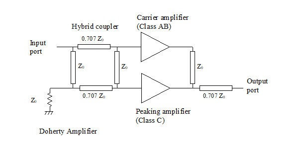
Microwaves101 Doherty Amplifiers

Description The Circuit Is Based Around Lm4702 Manufactured By National Semiconductors Amp Mj11029 Mj1102 Audio Amplifier Circuit Diagram Power Amplifiers

Amplifier Design Basics Electronics Notes
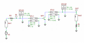
Rf Tutorial Lesson 10 Analyzing A Distributed Amplifier Using An Imported Rf Bjt Model Emagtech Wiki
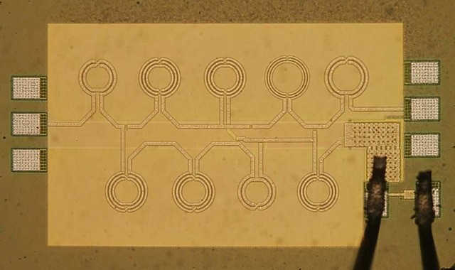
Microwaves101 Distributed Amplifiers

Microwaves101 Distributed Amplifiers
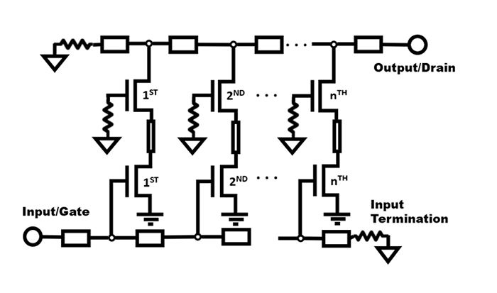
Distributed Amplifiers Are A Unique Circuit In High Frequency Microwave Engineering Qorvo
0 comments
Post a Comment